
PRIME MOVER
INDUSTRIES LIMITED
Top 9 Fuel Tanker Trailer Design Options for Multi-Compartment Fuel Transport
Single-compartment fuel tankers are a niche product in modern distribution. The overwhelming majority of fuel tanker trailers built for commercial operation in 2026 are multi-compartment units, because fuel distribution economics depend on delivering multiple grades — diesel, gasoline, kerosene, and sometimes lubricants — to multiple customers on a single route. A tanker that carries only one grade forces a separate trip for every product, and the deadhead miles between drops erase the margin.
But multi-compartment design is not simply a matter of dividing the tank into sections. The number of compartments, the capacity split between them, the internal baffle arrangement, the discharge system architecture, and the metering configuration all interact. A poorly specified compartment layout can leave a trailer unable to serve its intended customer base, while an over-specified layout adds weight, cost, and maintenance complexity without corresponding revenue benefit.
This guide covers the top 9 fuel tanker trailer design options for multi-compartment fuel transport in 2026. Each option includes the technical parameter, the trade-off it introduces, and the operating profile it suits. The focus is on design decisions that a buyer controls at the specification stage — not features that are fixed by regulation or by the chassis platform.
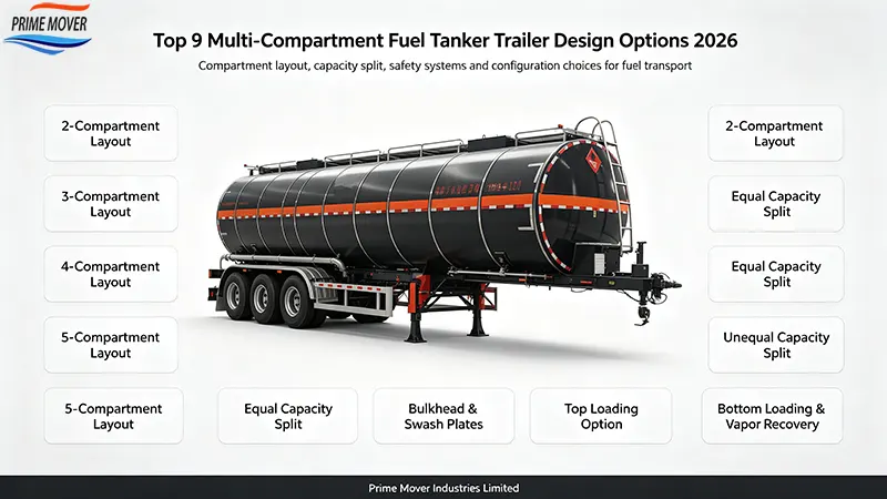
Design Option 1: Compartment Count — 2 to 6 Sections
The first design decision is how many compartments the tank will contain. The practical range for a 40,000 to 45,000 litre fuel tanker trailer is 2 to 6 compartments. Each compartment has its own manhole, filling connection, and discharge valve, and is separated from its neighbors by a bulkhead that also functions as a surge baffle.
| Compartment count | Typical per-compartment capacity | Best-fit operation | Design trade-off |
|---|---|---|---|
| 2 compartments | 18,000–22,000 L | Single-grade long-haul; two-grade bulk delivery | Fewest valves and connections; least route flexibility |
| 3 compartments | 12,000–15,000 L | General fuel distribution; three grades per trip | Balanced flexibility and complexity |
| 4 compartments | 9,000–11,000 L | Multi-station retail delivery | Higher valve count; more metering points |
| 5 compartments | 7,500–9,000 L | Dense urban distribution; aviation + road fuel mix | Reduced per-compartment payload; more seals to maintain |
| 6 compartments | 6,000–7,500 L | Complex distribution networks; small-drop deliveries | Maximum valve and seal count; highest tare weight |
The compartment count drives almost every other design decision. More compartments mean more bulkheads, more bottom valves, more vapor recovery connections, and more metering points. Each additional compartment adds roughly 150 to 250 kg of tare weight in bulkhead steel and valve hardware, and each bulkhead is a potential leak path that must be weld-tested at manufacture and inspected periodically.
The practical rule is to specify the fewest compartments that can serve the intended customer base. A distributor serving three fuel grades to three station types typically needs three compartments, not six. A six-compartment trailer is justified only when the route genuinely involves six discrete drops of different products.
Design Option 2: Capacity Split Strategy
Once the compartment count is fixed, the next decision is how to divide total capacity between compartments. Three strategies dominate: equal split, demand-weighted split, and flexible split.
| Split strategy | Example (45,000 L, 4 compartments) | Advantage | Limitation |
|---|---|---|---|
| Equal split | 11,250 / 11,250 / 11,250 / 11,250 L | Simple; interchangeable use; easier load planning | Cannot match asymmetric demand |
| Demand-weighted | 15,000 / 12,000 / 10,000 / 8,000 L | Matches actual product mix; fewer partial loads | Fixed; cannot adapt if demand shifts |
| Flexible (partitioned) | 15,000 / 15,000 / 15,000 L with transfer capability | Adaptable between products | Adds valve complexity; higher tare; limited by regulation |
Demand-weighted splitting is the most common commercial choice. A distributor whose sales mix is 60% diesel, 25% gasoline, and 15% kerosene will specify compartment capacities in roughly that ratio, so that a full load matches actual demand without leaving residual product at the end of the route.
Equal splitting is preferred by fleets that serve varied customers and cannot predict the product mix in advance. It sacrifices load optimization for operational simplicity. Flexible partitioning is technically possible but adds valve and transfer complexity that is rarely justified outside specialized aviation fuel operations.
Design Option 3: Tank Cross-Section Geometry
Multi-compartment fuel tankers use several cross-section geometries, and the choice affects capacity per unit length, center of gravity, and surge behavior.
| Cross-section | Characteristics | Surge behavior | Typical use |
|---|---|---|---|
| Elliptical | Low center of gravity; common in European designs | Moderate; free surface area relatively large | General fuel distribution |
| Circular | Uniform stress distribution; simplest fabrication | Higher center of gravity | Pressure vessels; smaller tankers |
| D-shaped / Double-D | Low profile with flat top for access | Lower center of gravity; reduced rollover risk | High-capacity road tankers |
| Rectangular with rounded corners | Maximum capacity per unit length | Highest free surface effect | Specialized bulk applications |
The elliptical and D-shaped cross-sections dominate multi-compartment fuel transport because they lower the center of gravity, which directly reduces rollover risk — the single most dangerous failure mode for a loaded fuel tanker. The D-shaped design also provides a flat top surface for manhole access and walkway installation, which improves operator safety during loading.
The cross-section choice interacts with compartment count. A tank with many compartments and a low-profile cross-section will have shallower compartments, which can reduce discharge efficiency if the fluidization or drainage path becomes too shallow for reliable bottom-valve operation.
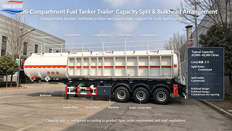
Design Option 4: Bulkhead and Baffle Arrangement
In a multi-compartment fuel tanker, the bulkheads that separate compartments also function as surge baffles. Their arrangement is both a regulatory requirement and an engineering choice.
ADR requires baffles in tanks exceeding 7,500 litres, and the bulkhead plates in a multi-compartment tanker typically satisfy this requirement for each compartment. For a 40,000-litre tank divided into four compartments, the three internal bulkheads plus the two end heads provide the surge-control structure. Where individual compartments are large — for example, two 20,000-litre compartments — additional transverse baffles within each compartment may be required.
| Arrangement | Bulkhead count | Surge control | Structural weight |
|---|---|---|---|
| 2 compartments | 1 internal bulkhead | Requires additional baffles within each 20,000 L section | Lower |
| 3 compartments | 2 internal bulkheads | Generally adequate without extra baffles | Moderate |
| 4 compartments | 3 internal bulkheads | Adequate; smaller free surface per section | Moderate to high |
| 5–6 compartments | 4–5 internal bulkheads | Excellent surge control | Highest |
Bulkhead design must also account for pressure equalization. Some multi-compartment designs include vent or equalization openings in the bulkheads to prevent pressure differential between compartments during temperature changes, while others maintain fully sealed compartments with independent venting. Sealed compartments are preferred when cross-contamination between products is a concern; equalized compartments simplify pressure management but require careful valve design.
Design Option 5: Discharge System Architecture
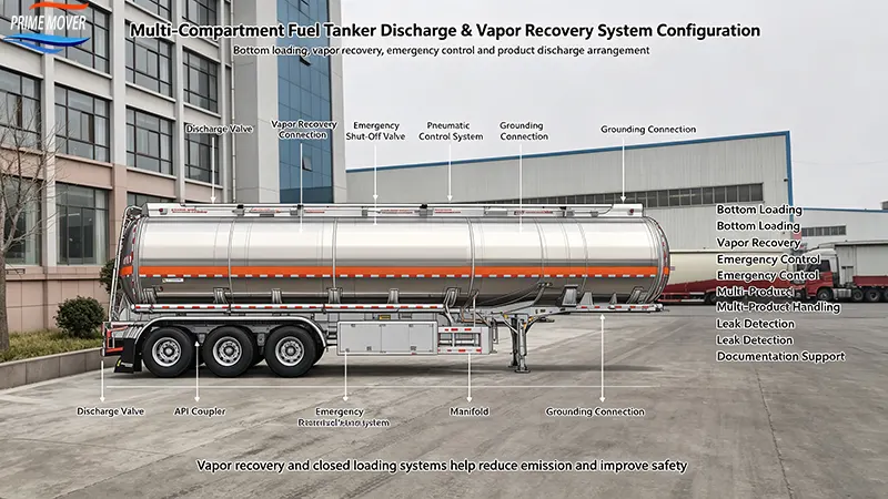
The discharge system is where multi-compartment design becomes operationally complex. Each compartment must be able to discharge independently, and the piping architecture determines how quickly and cleanly that can happen.
Independent vs. manifold discharge
| Architecture | Description | Advantage | Limitation |
|---|---|---|---|
| Independent per-compartment | Each compartment has its own discharge valve and outlet | No cross-contamination; simultaneous multi-product discharge | More valves, more outlets, higher cost |
| Manifolded discharge | Compartments feed a common manifold with selector valves | Fewer external connections; simpler hose management | Risk of residual cross-contamination; one product at a time |
| Hybrid | Independent outlets with optional manifold connection | Flexibility for both single and multi-product discharge | Highest complexity and tare weight |
For fuel distribution serving retail stations with dedicated product tanks, independent per-compartment discharge is the standard specification. It eliminates any possibility of mixing diesel into a gasoline drop, which would be a costly contamination event. The cost is additional valves, seals, and external connection points.
Manifolded systems are used where the trailer discharges into a single receiving line and product switching happens at the receiving end. They reduce external hardware but require rigorous flushing procedures between products.
Design Option 6: Bottom Loading System Configuration
Modern fuel tanker trailers are loaded from the bottom, not the top. Bottom loading reduces vapor generation, improves loading speed, and allows vapor recovery to be integrated into the loading process. The design option here is how the bottom loading system is configured across compartments.
| Configuration | API coupler arrangement | Loading speed | Vapor recovery integration |
|---|---|---|---|
| Single-point bottom loading | One API coupler feeding a manifold | Sequential compartment filling | Single vapor return point |
| Multi-point bottom loading | One API coupler per compartment | Parallel filling possible | Per-compartment vapor return |
| Hybrid with selector valves | Fewer couplers with compartment selection | Controlled sequential | Shared vapor return with isolation |
Multi-point bottom loading is the standard for high-throughput fuel terminals because it allows all compartments to fill simultaneously, cutting loading time by 60% to 70% compared with sequential filling. The API coupler standard (API RP 1004) governs the connection interface, and each coupler must be fitted with a dry-break valve to prevent spillage on disconnection.
The bottom loading configuration must also include overfill protection. Each compartment requires a sensors that signals the loading system to stop when the compartment reaches its fill limit, typically 95% of capacity to leave ullage space for thermal expansion.
Design Option 7: Vapor Recovery System Design
Vapor recovery is both an environmental requirement and an operational safety feature. As a compartment fills with liquid, displaced hydrocarbon vapor must be captured and returned to the terminal rather than vented to atmosphere. The design option is the vapor recovery architecture.
| System type | Vapor recovery efficiency | Complexity | Typical regulatory driver |
|---|---|---|---|
| Passive venting | 0% (vapor released) | Lowest | Not compliant in most regulated markets |
| Single-point vapor recovery | 85–92% | Moderate | Stage I vapor recovery requirements |
| Per-compartment vapor recovery | 95–98% | High | Strict air quality jurisdictions |
| Closed-loop with vapor balance | 98%+ | Highest | Terminals with vapor balance systems |
Vapor recovery systems must be designed to prevent cross-contamination between compartments, because recovered vapor from a gasoline compartment must not be routed into a diesel compartment’s vapor space. Per-compartment vapor recovery with isolation valves is the safest architecture for multi-product tankers, despite its higher complexity.
The vapor recovery connection point is typically a 4-inch camlock or API adapter located near the bottom loading couplers. The system must include flame arresters and pressure/vacuum relief valves to prevent over-pressurization or vacuum collapse during loading and discharge.
Design Option 8: Material Selection and Its Effect on Compartment Design
The choice between carbon steel and aluminum affects multi-compartment design more than it affects single-compartment design, because the weight of the bulkheads multiplies with compartment count.
| Parameter | Carbon steel multi-compartment | Aluminum multi-compartment |
|---|---|---|
| Bulkhead weight per internal division | ~180–250 kg | ~60–90 kg |
| 4-compartment tank tare (45,000 L) | ~9,500–10,500 kg | ~6,200–7,000 kg |
| Payload advantage | Baseline | +2,500–3,500 kg per trip |
| Weld inspection complexity | Standard procedures | Requires aluminum-certified welding and NDT |
| Corrosion at bulkhead welds | High risk; coating must extend into compartment interiors | Low; natural oxide layer |
Aluminum’s weight advantage compounds with compartment count. A 6-compartment carbon steel tanker carries five heavy internal bulkheads; the same configuration in aluminum saves roughly 600 to 800 kg on bulkheads alone, on top of the shell and head weight savings. For a multi-compartment trailer operating near the legal gross weight limit, that differential translates directly into additional payload on every trip.
The trade-off is weld complexity. Aluminum bulkheads must be welded with a qualified procedure, and the heat-affected zone must be inspected for porosity and lack of fusion. Carbon steel bulkheads are more forgiving to fabricate but require internal coating to prevent corrosion in the vapor space above the liquid line.
Design Option 9: Metering and Monitoring Configuration
The final design option is how the multi-compartment tanker measures and reports what it is carrying and what it has discharged. This is where the difference between a basic tanker and a commercially competitive one becomes visible to the fleet operator.
| Configuration | Capability | Accuracy | Cost impact |
|---|---|---|---|
| Mechanical float gauges | Per-compartment level indication | ±2–3% | Lowest |
| Electronic level sensors | Digital per-compartment level and volume | ±0.5–1% | Moderate |
| Electronic + flow meters | Discharged volume per compartment per drop | ±0.2–0.5% | Higher |
| Full telematics integration | Real-time level, discharge, location, and tamper alerts | ±0.2–0.5% plus event logging | Highest |
For multi-compartment fuel tankers, per-compartment metering is not a luxury. It is the mechanism that proves what was delivered to each customer and detects unauthorized discharge or theft. A 4-compartment tanker delivering to four stations in a single route without per-compartment metering cannot reconcile its load against deliveries, which creates disputes with customers and leaves product loss undetected.
Electronic level sensors with telematics integration are becoming the standard for fleets operating more than three tankers. The telematics market for trailer monitoring is growing at 11.5% annually, and the ROI case is straightforward: fuel theft elimination of up to 99% and per-drop delivery verification typically recover the system cost within 12 to 18 months.
Design Options Comparison Summary
| Design option | Key decision | Primary trade-off | Best-fit profile |
|---|---|---|---|
| 1. Compartment count | 2 to 6 sections | Route flexibility vs. tare weight and complexity | 3–4 compartments for general distribution |
| 2. Capacity split | Equal, demand-weighted, or flexible | Load optimization vs. operational simplicity | Demand-weighted for known product mix |
| 3. Cross-section | Elliptical, circular, D-shaped | Capacity vs. center of gravity | D-shaped for high-capacity road tankers |
| 4. Bulkhead arrangement | Bulkheads as baffles; sealed or equalized | Surge control vs. cross-contamination risk | Sealed compartments for multi-product |
| 5. Discharge architecture | Independent vs. manifolded | Contamination isolation vs. hardware cost | Independent per-compartment for retail delivery |
| 6. Bottom loading | Single-point vs. multi-point | Loading speed vs. coupler count | Multi-point for high-throughput terminals |
| 7. Vapor recovery | Single-point vs. per-compartment | Recovery efficiency vs. complexity | Per-compartment with isolation for multi-product |
| 8. Material | Carbon steel vs. aluminum | Payload vs. weld complexity and cost | Aluminum for high-mileage weight-sensitive fleets |
| 9. Metering | Mechanical vs. electronic + telematics | Accuracy and theft prevention vs. cost | Electronic + telematics for fleets over 3 tankers |
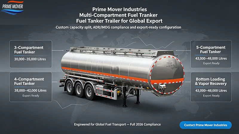
Prime Mover Industries: Configurable Multi-Compartment Fuel Tanker Trailers
Prime Mover Industries is a Hong Kong-based manufacturer and global exporter established in 2014. Its fuel tanker trailer line is built around configurable multi-compartment architecture, allowing buyers to specify compartment count, capacity split, discharge architecture, and metering configuration against actual route requirements rather than accepting a fixed export model.
| Design parameter | Prime Mover standard | Optional configuration |
|---|---|---|
| Compartment count | 2–4 | Up to 6 compartments |
| Capacity split | Equal split | Demand-weighted per customer specification |
| Tank cross-section | Elliptical | D-shaped low-profile |
| Tank material | Q345B carbon steel | 5182 aluminum alloy |
| Discharge architecture | Independent per-compartment | Manifolded with selector valves |
| Bottom loading | API RP 1004 couplers | Multi-point with overfill sensors |
| Vapor recovery | Single-point with flame arrester | Per-compartment isolated recovery |
| Metering | Mechanical float gauges | Electronic sensors + telematics integration |
| Emergency valves | Pneumatic bottom valves | Remote-controlled with fusible element |
For buyers specifying multi-compartment fuel tanker trailers in 2026, Prime Mover Industries provides factory-direct pricing, third-party inspection through SGS or BV, full export documentation, and the specification flexibility to match compartment architecture to the actual distribution network. The company serves clients across Africa, Southeast Asia, and the Middle East, where multi-product fuel distribution is the dominant operating model.
Conclusion
The top 9 fuel tanker trailer design options for multi-compartment fuel transport — compartment count, capacity split, cross-section geometry, bulkhead arrangement, discharge architecture, bottom loading configuration, vapor recovery design, material selection, and metering configuration — determine whether a trailer can serve its intended route profitably or becomes an expensive asset that cannot match the product mix it was bought for.
The practical specification sequence is: define the number of product drops and the product mix first, then set compartment count and capacity split to match, then select discharge and vapor recovery architecture that prevents cross-contamination, then choose material based on annual mileage and weight sensitivity, and finally specify metering and telematics to match fleet size.
For buyers in 2026, the correct multi-compartment fuel tanker trailer is not the one with the most compartments or the most advanced metering. It is the one whose compartment architecture matches the distribution network it will actually serve. That match — not the headline capacity number — is what determines return on investment in multi-compartment fuel transport.
Written by
Prime Mover Industries
Editor Wang
WhatsApp:+86-189 5386 6163
Email:wlei66@126.com
PRIME MOVER
INDUSTRIES LIMITED